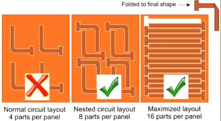
Did you know that material utilization is one of the biggest cost drivers on flex PCB?

Nesting circuits and maximising
the panelization will result in huge cost savings.

See the example below. A panel with a normal circuit layout with 4 parts, can with nested circuit layout give a 50% increase of parts per panel, and by maximizing the circuit layout improve even more, thus result in huge cost savings.

So, how should the conductor routing be?

  • Conductors should not be placed directly over each other. ( z-axis )
  • The number of layers in the bend area should be kept to a minimum.

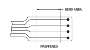
  • Vias & PTHs in bend areas should be avoided.
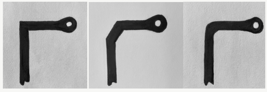
  • Curved tracks are preferable.
  • Tracks/Gaps should be uniform.

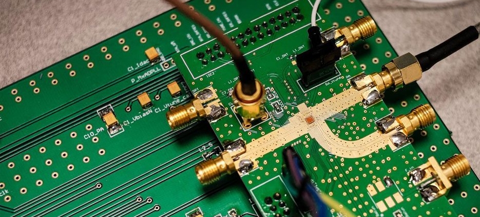
Something to remember when you look into cost savings on your flex PCB design. We have been involved in thousands of Flex and Flex-Rigid designs over the year.
Feel free to reach out to us when you are designing a product in need of any of these. On of our Technical Advisors might be able to assist, and see solutions not considered before.

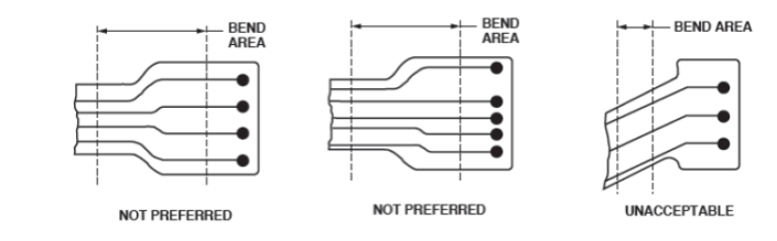
They have sketched up the best, better and the one conductor routing to avoid, below.

AVOID                                                                                BETTER                                                                      BEST

  1. PCB material types

FR-4

HDI board

Metal core

High tg material

  1. Your electronic project with various PCB material

With the development of electronic technology, the circuit board plays such an important role in electronic products, medical devices, industrial equipment, safety and security equipment and so on. So what kinds of PCB materials you choose will make a great effect on the functionality, manufacturability and life cycle of your board.

FR-4

In fact, FR-4 refers to a grade of material rather than a material, which is a composite material for glass-reinforced epoxy laminate material. FR-4 is made up of woven fiberglass cloth with an epoxy resin binder that is flame resistant. And FR stands for flame retardant, it denotes that the material complies with the standard UL94V-0.

Note: FR-4 material provides the fundamental standard for PCB substrates, keeping a widely effective balance between cost, durability, performance, manufacturability, as well as electrical properties.

Standard FR-4: save product costs and is affordable and effective for many applications.

Metal core: if you are making a electronic project of LED based products, choose the metal core in your boards. What’s more, metal core PCB is more and more common in a variety of lighting applications-for home, workplace, and vehicle.

HDI material: HDI technology is a good solution for smaller and lighter products, high-tech applications, denser BGA and QFP packages, as well as lowered heat transfer included stress.

High TG: If there is a higher power density in electronic products and heat generation will tend to disturbing heat sink or other parts of the products, so high Tg PCB is the best solution. What is more, you can find that high Tg PCBs are applied in electronic industries which can operate in relatively high temperatures as high Tg PCB are more and more popular in recent years.


PCBs come in varying types, shapes, and sizes. They are always being modified to fit modern technological requirements. Aluminium PCBs are a type of PCBs that has been around for quite some time, in fact, their first development can be traced back to the 1970s. They are quite different from your ordinary PCBs.

For aluminum PCBs, there is much you need to know. They have many differences from ordinary PCB boards. The PCB contains a copper-clad lamination and aluminum-based metalcore.  Other than that, aluminum in itself acts as a suitable metal substrate and is less costly.

What is Aluminium PCB?

Among the metal core PCBs, aluminum PCBs are the most commonly found ones. As the name suggests the base material used is aluminum in the form of a core along with standard FR4. Due to its material design, it works brilliantly in terms of heat dissipation and so it ideal for applications that demand more power. The first aluminum PCBs were developed in the 1970s after which their applications increased drastically. In modern times they are used in LED lighting, power systems, and automotive systems. Due to their wide-scale use, it is necessary as a PCB hobbyist to have a basic understanding of aluminum PCBs.

Composition & Manufacturing 

We’ve discussed before that aluminum PCBs contain aluminum as one of their base materials, in fact, it is the critical component of the metalcore. Along with this, there is a thin layer of thermal dielectric material and electrically insulating material. In total, we can identify 3 layers i.e

  • Circuit Layer: The circuit layer is composed of copper foil.
  • Thermal Insulation Layer: Or the dielectric layer. This layer is both electrically insulating as well as thermally conductive.
  • Base Layer: The base is composed of an aluminum alloy substrate.

As for the manufacturing of Aluminum PCBs, the thin dielectric layer is added between the circuit and base layers. Once this is positioned, the circuit layer composed of copper foil is etched to give you the circuit pattern. The metal base at the core will help work with the

  • High Thermal Conductivity Aluminum PCBs

These PCBs have excellent thermal conductivity. It gets this quality from its material design. The insulating layer used here is an epoxy resin material that allows for it.

  • High-Frequency Aluminum PCBs

In these PCBs, the insulating layer is made up of polyolefin/polyimide, or fiberglass between an epoxy resin. This allows for higher levels of flexibility in the PCB.

Advantages of Aluminium PCBs

There a number of advantages of Aluminum PCBs that make them stand out. Some of these are enlisted below:

  1. Alunumium itself is non-toxic and recyclable, therefore proving aluminum PCBs to be environmentally friendly.
  2. As we’ve discussed before, aluminum PCBs are ideal due to their heat dissipation capabilities. High levels of heat can damage devices so this makes it a major plus point for aluminum PCBs.
  3. Aluminum PCBs are more durable as the material is far more sturdy and can help reduce the chances of breakage.
  4. Aluminum is also a pretty lightweight material reducing the overall weight of the printed circuit board.
  5. Aluminum PCBs are generally more thermally conductive as opposed to the standard thermal glass PCBs.